
Creating a mesh network topology in Cisco Packet Tracer involves connecting each device to every other device in the network. Here's a step-by-step guide to implementing a mesh topology using Cisco Packet Tracer:
1. **Open Cisco Packet Tracer:**
- Launch Cisco Packet Tracer on your computer.
2. **Create a New Network:**
- Click on "File" in the menu and select "New" to create a new network project.
3. **Add Devices:**
- Drag and drop the devices you want to include in your mesh network from the device panel to the workspace. Common devices for a mesh network include routers and switches.
4. **Connect Devices:**
- Use the appropriate cables to connect each device to every other device in the network. In a mesh topology, each device should be directly connected to every other device.
5. **Configure IP Addresses:**
- Double-click on each device to open its configuration window.
- Assign IP addresses to the interfaces of each device. Make sure that the devices can communicate with each other using these IP addresses.
6. **Configure Routing (if necessary):**
- If you are using routers in your mesh network, configure routing protocols or static routes to ensure proper communication between devices.
7. **Test Connectivity:**
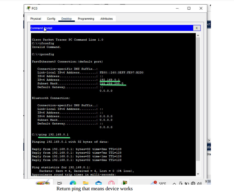
- Use the "Command Line Interface (CLI)" of each device to test the connectivity between devices. Ping commands can be used for this purpose.
8. **Save Your Project:**
- Save your project to ensure that your mesh topology configuration is preserved for future use.
Here's an example of a simple mesh network with three routers (R1, R2, R3):
```
R1
/ \
/ \
R2-----R3
```
In this example, R1 is directly connected to R2 and R3, and R2 is directly connected to R1 and R3. Similarly, R3 is directly connected to R1 and R2.
Remember that in a real-world scenario, the complexity of the mesh network can increase as you add more devices, and the configuration may involve more advanced settings depending on your specific requirements.

Here we can take 4 pc in cisco packet tracer
and 4 switches. You can rename them if you want.But thats not necessery .
For data transmission we have to create ip addresses of each pc and ping each other.
For pc0 we can set the ip 192.168.0.1
For pc1 we can set the ip 192.168.0.2
For pc 2 we can set the ip 192.168.0.3
for pc 3 we can set the ip 192.168.0.4
Then we can check transmission from one pc to anoher.
LAB REPORT FORM
Experiment No: 01
Title:Mesh Topology Implementation for Efficient Data
Transmission in Cisco
Packet Tracer
Abstract:
The project aims to implement a mesh topology within Cisco
Packet Tracer to optimize data
transmission in a network environment. Mesh topology offers
robustness and redundancy by providing
multiple paths for data to traverse, enhancing the overall
reliability of the network. This document
outlines the steps involved in setting up and configuring a
mesh topology using Cisco Packet Tracer.
Introduction:
In modern networking, the need for reliable and efficient
data transmission is paramount. Mesh
topology, characterized by its interconnectivity, offers a
solution by creating redundant paths between
devices. This ensures that even if one link fails, data can
still find an alternative route, minimizing
downtime and enhancing network resilience. The
implementation of mesh topology in Cisco Packet
Tracer provides a simulated environment to understand its
benefits and challenges.
Process:Network Design:

Cisco Packet Tracer Setup:
• Launch Cisco Packet Tracer and create a new project.
• Select networking devices (routers and switches) from the
available options.
Configuration:

• Assign IP addresses to devices.
• Configure routing protocols (e.g., OSPF) for dynamic path
selection.
• Establish connections between devices to form a mesh.
Click PC0 then click
desktop set ipv4 like 192.168.0.1/2/3/4
Testing:
• Simulate network scenarios to validate redundancy and path
optimization.
• Analyze packet flow and network behavior under various
conditions.
Return ping that
means device works
Results
Demonstrate the effectiveness of mesh topology in:
• Reducing single points of failure.
• Improving overall network performance.
• Providing resilience against link failures.
Conclusion:
Summarize the key findings and highlight the benefits of
implementing mesh topology for data
transmission. Discuss potential real-world applications and
considerations for deploying mesh
networks. Conclude with insights gained from the project and
suggestions for further exploration.
This outline provides a framework for your documentation. As
you proceed with the implementation in
Cisco Packet Tracer, you can fill in the details for each
section.
For better understand video is bellow


%20standing%20in%20a%20cyberpunk%20environment%20w.webp)


0 Comments