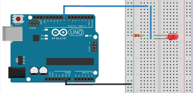
experiment to implement digital input and output using Arduino

At first make circuit diagram as bellow


Materials:

  • Breadboard
  • Arduino Uno
  • LED
  • 220 ohm resistor
  • Jumper wires

 Aim:

The aim of this experiment is to implement and understand the basic concepts of digital input and output using an Arduino. By connecting an LED to the Arduino and programming it to blink, we can explore how to control digital outputs.


Steps:

  1. Connect the breadboard to the Arduino. The Arduino Uno has rows of male pins that fit into the female sockets of the breadboard.

  2. Connect the resistor to the breadboard. One leg of the resistor should be placed in any row of the breadboard. The other leg should be placed in a different row.

  3. Connect the cathode (short leg) of the LED to the ground (GND) pin of the Arduino. The GND pin is one of the outer pins on the Arduino Uno that has a ground symbol next to it.

  4. Connect the resistor to the cathode (short leg) of the LED. Insert one leg of the LED into the same row of the breadboard that the short leg of the resistor is in.

  5. Connect the anode (long leg) of the LED to a digital output pin of the Arduino. Digital output pins are any of the pins on the Arduino Uno that are not designated as GND or 3V3. A common pin to use is pin 13. Insert the leg of the LED into the same row of the breadboard that the other leg of the resistor is in.

  6. Connect the Arduino to your computer using a USB cable.

  7. Write and upload code to the Arduino. Here is a simple code that will blink an LED on and off:

int ledPin = 8; // Define the LED pin

void setup() {
  pinMode(ledPin, OUTPUT); // Set the LED pin as an output
}

void loop() {
  digitalWrite(ledPin, HIGH); // Turn the LED on
  delay(1000); // Wait for 1 second
  digitalWrite(ledPin, LOW); // Turn the LED off
  delay(1000); // Wait for 1 second
}
  1. Open the Arduino IDE software. The Arduino IDE is a free software program that you can use to write and upload code to your Arduino. You can download it from the Arduino website https://www.arduino.cc/en/software.

  2. Copy and paste the code into a new sketch. A sketch is a file that contains your Arduino code.

  3. Connect your Arduino to your computer using a USB cable.

  4. Click the "Verify" button in the Arduino IDE. This will check your code for errors.

  5. Click the "Upload" button in the Arduino IDE. This will upload your code to your Arduino.                                                                                                                                                                                                                                                                                                                                         


  6. The LED should start blinking on and off.


To implement digital input and output using an Arduino as shown in the image, follow these steps:

in clear 

Steps:

  1. Connect the Arduino to Your Computer:

    • Connect the Arduino Uno to your computer using a USB cable.
  2. Setup the Breadboard:

    • Place the LED on the breadboard.
    • Place the 220-ohm resistor in series with the LED.
  3. Make the Connections:

    • Connect one end of the resistor to the longer leg (anode) of the LED.
    • Connect the shorter leg (cathode) of the LED to the ground rail (GND) of the breadboard.
    • Connect a jumper wire from digital pin 8 on the Arduino to the other end of the resistor.
    • Connect a jumper wire from the GND pin on the Arduino to the ground rail (GND) of the breadboard.
  4. Arduino Code:

    • Open the Arduino IDE on your computer.
    • Write the following code to control the LED:
code:

// Define the LED pin const int ledPin = 8; void setup() { // Initialize the digital pin as an output pinMode(ledPin, OUTPUT); } void loop() { // Turn the LED on digitalWrite(ledPin, HIGH); delay(1000); // Wait for a second // Turn the LED off digitalWrite(ledPin, LOW); delay(1000); // Wait for a second }
  1. Upload the Code:
    • Select the correct board and port in the Arduino IDE.
    • Click the upload button to upload the code to the Arduino.

Explanation:

  • Pin Mode:
    • pinMode(ledPin, OUTPUT); sets the pin connected to the LED as an output.
  • Digital Write:
    • digitalWrite(ledPin, HIGH); turns the LED on by setting the pin to HIGH.
    • digitalWrite(ledPin, LOW); turns the LED off by setting the pin to LOW.
  • Delay:
    • delay(1000); creates a 1-second delay between turning the LED on and off.

This simple experiment demonstrates how to control a digital output (LED) using the Arduino. You can expand this experiment by adding a button to control the LED, introducing the concept of digital input.


Conclusion:

In this experiment, we successfully implemented a digital output using an Arduino. We connected an LED to the Arduino and programmed it to blink at 1-second intervals. This demonstrated how to control digital signals using the `digitalWrite()` function and set pin modes using the `pinMode()` function. This fundamental knowledge is essential for building more complex circuits and projects involving digital inputs and outputs.

Post a Comment

0 Comments